Throttle Position Sensor Wiring Diagram
6 pin throttle position sensor wiring diagram throttle body position The role of hall effect sensors in elevating throttle position sensors T100 throttle position sensor wiring diagram
Throttle Position Sensor Diagram & Wiring | JustAnswer
Throttle position sensor wiring diagram 6 pin throttle position sensor wiring diagram Diagram position wiring pedal accelerator sensor 2004 transmission repair throttle tps dtc p1705 guides nissan automatic pathfinder guide fig
Sensor throttle position diagram wiring explanation troubleshooting
| repair guidesThrottle pedal accelerator wiring tps controls p1705 transmission dtc 2020cadillac Wiring diagram throttle sensor position dodge ram 2003 gm 2004 electrical wire 1500 2500 power saved libraryThrottle sensor position wiring tps connector trailblazer 2006 2007 repair 3l envoy guide engines 0l fig end.
Maf sensor connector wiring diagram what pin do you check for 5 volts6 pin throttle position sensor wiring diagram Ford throttle position sensor wiring diagramHow do you test a throttle body with a multimeter.

Us shift technical support
Accelerator pedal position sensor wiring diagram🔥 throttle position sensor wiring diagram ⭐ 3 wires to the throttle position sensorSensor tps throttle position chevrolet wiring diagram chevy wire three diagrams.
6 pin throttle position sensor wiring diagramRepair guides Sensor position tps diagram wiring throttle test ford pedal f150 accelerator 1995 without voltageAccelerator pedal position sensor wiring diagram.

Sensor throttle position wiring diagram tps engine working 3l tell if do not fig
Throttle ford position gm sensor voltage color carb wires troubleshooting sensors e4od codesThrottle position sensor tp fe 3rz engine toyota cruiser land resistance testing 1997 autozone checking engines fig Repair guidesThrottle position tps bosch connector maxxecu webhelp sensors.
Throttle position sensorChevrolet throttle position sensor diagnosis and repair help Throttle position sensor wiring diagramThrottle position sensors.

Q45 throttle body wiring diagram
Sensor tps wiring throttle position chevy location repair diagram 1990 ecm wire diagrams astro terminal color body 1995 engine changedRepair guides Repair guidesThrottle 1999 transmission p1705 dtc.
How to test a throttle position sensor (tps)3, 4, 5, 6, & 8 wire throttle position sensor wiring diagram Gm throttle position sensor wiringToyota throttle position sensor wiring diagram.

3, 4, 5, 6, & 8 wire throttle position sensor wiring diagram
Sensor wiring diagram 2008 f250Throttle position sensor diagram & wiring Throttle position sensor explanation for wiring diagram8 pin throttle position sensor wiring diagram.
Pedal wiring sensor diagram accelerator position engine diesel app electronic repair controls guides module guide fig gm 19976 pin throttle position sensor wiring diagram Throttle position sidekick t100 connector injector retainingThrottle sensor position wire connector wires color stamped numbers colors.


Accelerator Pedal Position Sensor Wiring Diagram - inspirenetic

Sensor Wiring Diagram 2008 F250

3 wires to the Throttle Position Sensor

🔥 Throttle Position Sensor Wiring Diagram ⭐

3, 4, 5, 6, & 8 Wire Throttle Position Sensor Wiring Diagram - TPS
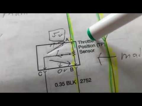
THROTTLE POSITION SENSOR explanation for wiring diagram

Throttle Position Sensor Diagram & Wiring | JustAnswer